Autonomous 3D-Printer Unloader Cell
MSc RASID group project: a 5-DoF robotic cell that autonomously detaches and racks finished print beds, built around a hardware-in-the-loop architecture
Autonomous 3D-Printer Unloader Cell
Overview
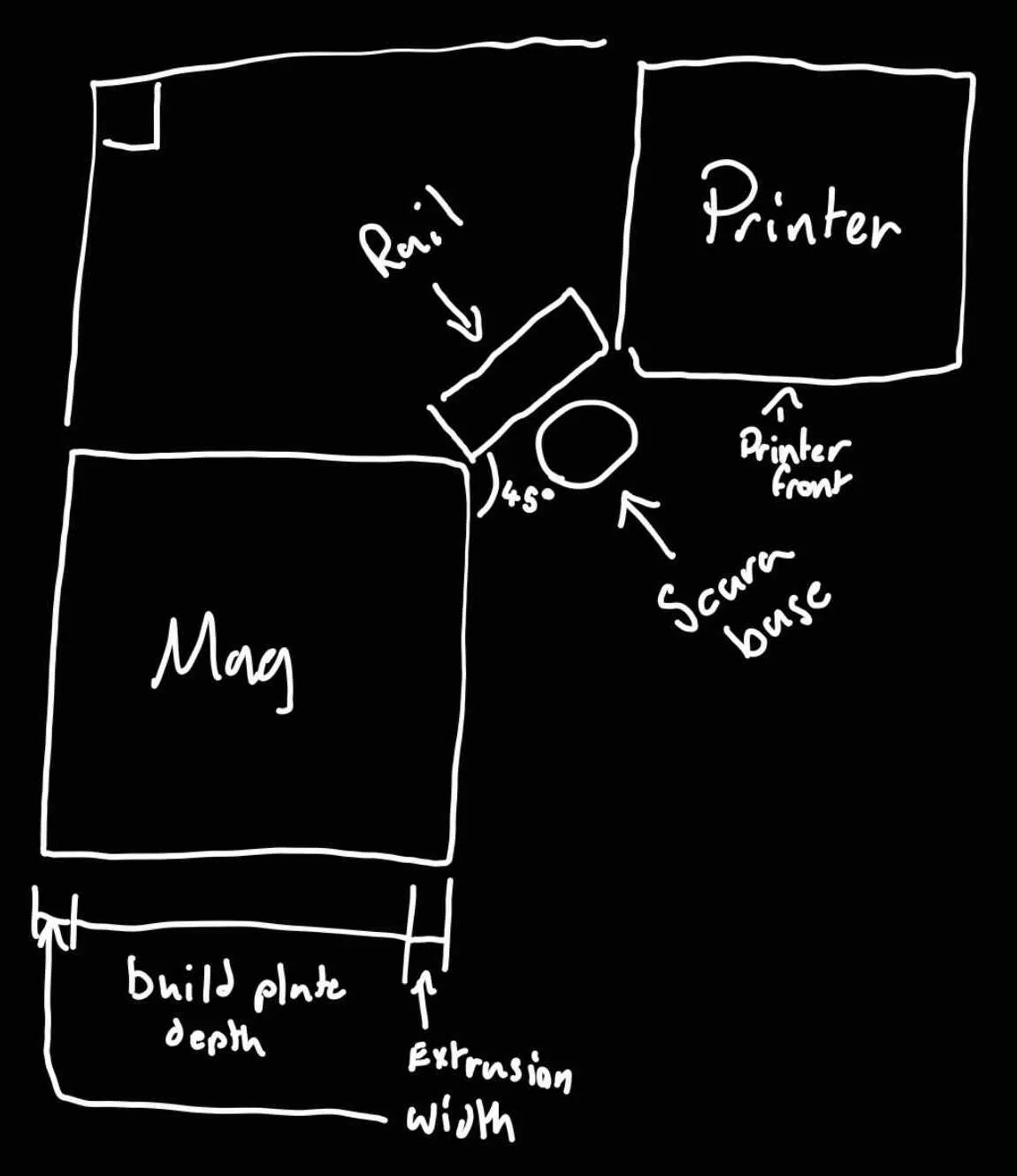
A 5-DoF robotic cell that autonomously detaches a finished print bed from a Prusa MK4S and racks it for cooling, built for the MSc Robotic & Autonomous Systems Design and Integration Project (RASID, ME52084) at the University of Bath.
This was a group project in which I was Software & Control Lead, owning the system integration and integration of the physical end-effector — the only hardware element of the build. The completed cell achieved a 90.3 s hardware-in-the-loop cycle against a 120 s target.
The Cell
- 5 degrees of freedom: an eduScara 4-DoF SCARA plus a custom NEMA 17 vertical rail.
- Sequence: detect the finished bed, lift it clear of the printer, and rack it for cooling.
Technical Implementation
Architecture: hardware and simulation made interchangeable
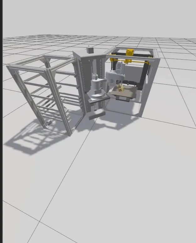
The defining design decision was to containerise the whole stack under Docker Compose so that every subsystem (end-effector firmware, plate-alignment perception, SCARA controller, simulation) ran as its own segmented container. This gave the cell two run modes: full-sim (every subsystem running as a container, no hardware connected) and demo (everything simulated except the physical end-effector, which executes its real motions and streams real sensor feedback). The end-effector was the only physical hardware element of the build.
That interchangeability is exactly the pattern used to validate hardware you cannot test in its final environment: bring real components online one at a time against an otherwise-simulated system. It is also what made the integration tractable as a group project, since sub-systems could be developed and tested independently before meeting on real hardware.
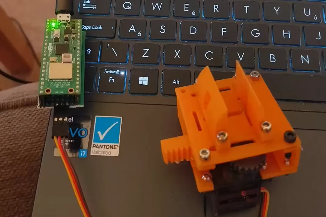
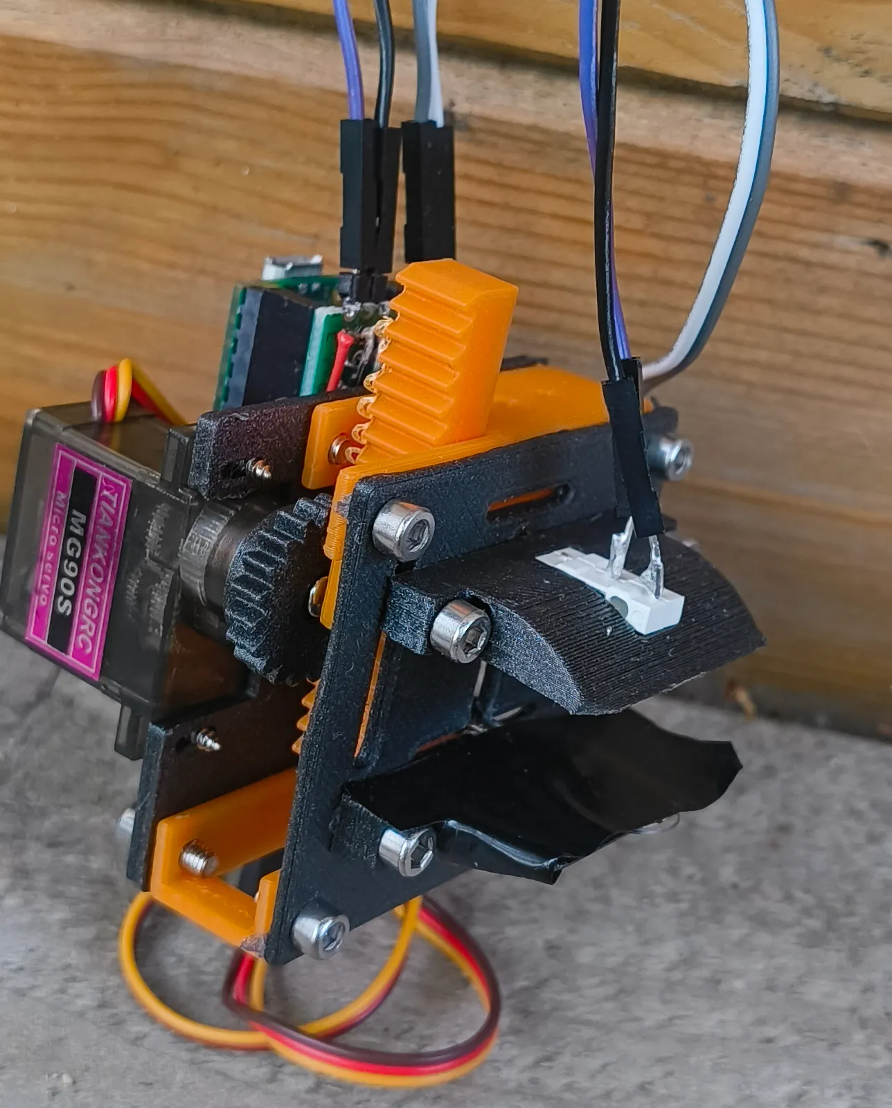
At the centre of it sat a custom ros2_control hardware interface written in C++, bridging an STM32F446RE motion-controller fork (extended protocol v2) and a Raspberry Pi Pico 2W end-effector firmware (servo, pressure sensor, and microswitch).
Inverse kinematics: dropping MoveIt for a closed-form solver
I started with a MoveIt baseline but dropped it mid-project once it was clear its planning overhead and integration weight were not justified for a fixed 2R geometry. The replacement was a hand-written closed-form 2R inverse-kinematics solver in Python (NumPy): deterministic, dependency-free, and far faster per solve. The vertical rail used cubic acceleration profiling (NEMA 17, 8× microstep, 1000 steps/mm over 328 mm of travel).
Perception: synthetic data by choice
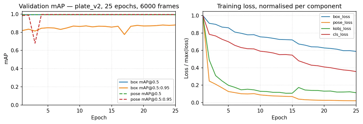
There was no labelled dataset of print beds to train on, so rather than collect and label real images I rendered synthetic data in Gazebo Harmonic — which gave pixel-perfect keypoint labels for free and full control over lighting and pose variation. I trained a YOLOv8n-pose plate detector end-to-end on 6,000 frames (mAP@0.5:0.95 = 0.995), chosen as the model that best fit my laptop’s training budget. A keypoint → Procrustes planar-pose solver achieved ±1 mm in simulation.
Technologies
- Robotics: ROS 2, a custom
ros2_controlC++ hardware interface, micro-ROS - Languages: Python (IK, control, perception), C++ (embedded firmware on STM32 + Pico)
- Perception: YOLOv8n-pose, Gazebo Harmonic (synthetic-data generation), OpenCV
- Infrastructure: Docker Compose (full-simulation and HITL run modes)
- Hardware: eduScara SCARA, custom NEMA 17 vertical rail, STM32F446RE, Raspberry Pi Pico 2W, servo + pressure-sensor + microswitch end-effector
Results
- 90.3 s hardware-in-the-loop cycle versus a 120 s target.
- The only fully functional demo in the cohort.
- Earned the top presentation and report grades for the module.
An early simulation test of the unloading cycle, shown at 2× speed.
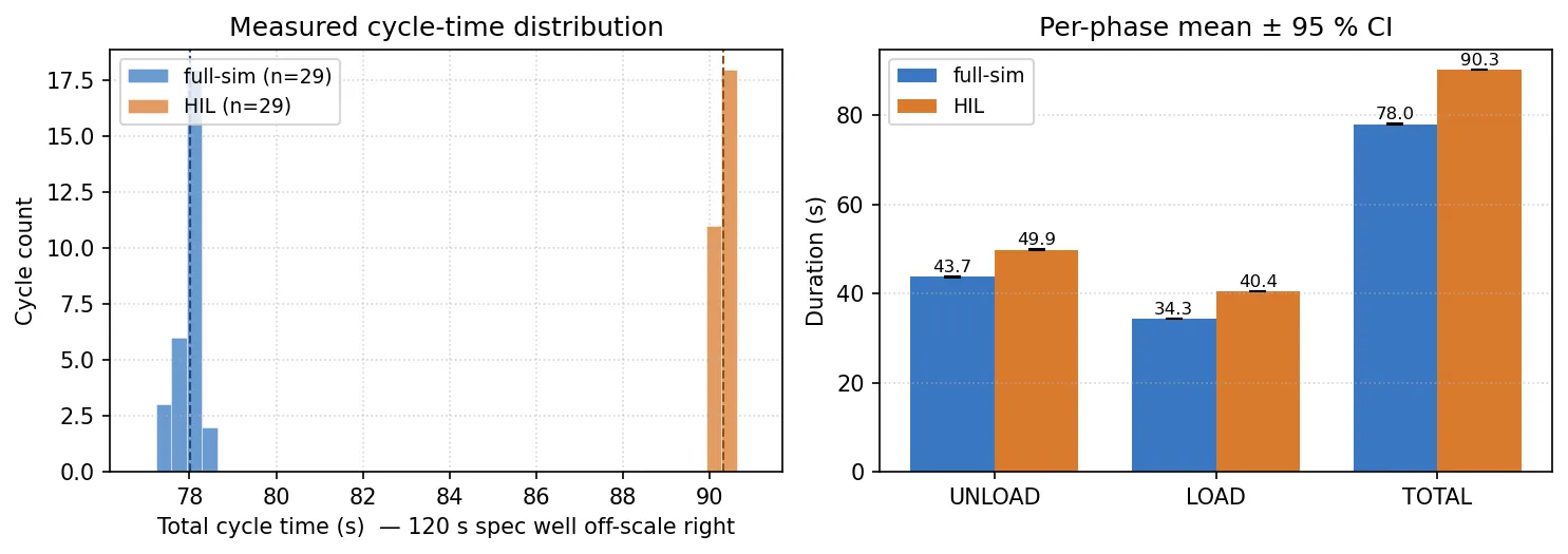
The result held together because of the segmented, swap-in architecture: a more monolithic build would have been far harder to integrate and test under the project’s time constraints.
Honest Notes
- The ±1 mm pose accuracy figure is a simulation result; end-to-end pose accuracy on the physical cell was never characterised.
- In demo (hardware-in-the-loop) mode the only physical hardware was the end-effector; the SCARA motion and the rest of the cell ran in simulation. It was not a full hardware end-to-end run of every component.
References
- The 4-DoF SCARA base is the EduSCARA open-source platform: EduSCARA: An open source RRPR educational SCARA platform (HardwareX, 2026).